4. Laser Cutting & 3D Printing Repair#
This week we had the opportunity to work on Laser Cutting and 3D Printing Repair.
4.1. Laser Cutting#
GOAL: Learn how to design, prepare 2D CAD files and laser cut them.
On monday, we started with a brief overview of what Laser Cutting is, particularly focusing on safety in this area.
Essential Precautions
| Before | During | After |
|---|---|---|
| Make sure you know what material you are cutting (in my case was raw wood) | Do not stare directly at the laser beam | Don’t open the machine until there is no smoke inside |
| Always activate the compressed air | Stay near the machine until the cutting is complete | Remove any cutting residue |
1. Install Inkscape#
It is a 2D vector image tool. To install it, click on this link. To learn how to use this program, I read this tutorial.
2. How to lasercut?#
I learned how to use both the Epilog Fusion Pro 32 and the Lasersaur. I found the Epilog to be more intuitive and easier to manage. However, since many people wanted to use that same machine, I had no choice but to do all my work with the Lasersaur. It was a bit challenging at first, but I managed with some help.
The steps were:
- Save the file in .svg format.
- Copy the file to a USB drive.
- Open the file on the computer connected to the Lasersaur.
- Launch the Driverboard application for laser cutting and open the file there.
- Choose the material you want to work with and place it in the machine.
- Press offset to adjust your design’s position if needed. If you need to reposition the material, use the Move option.
- Set the speed and power for each color used in your design.
I encountered some issues with colors not appearing correctly in the laser cutting app. While the colors were visible in Inkscape, they didn’t show up in the app. The issue was that I used the Fill tool instead of the Stroke Paint tool. If you have trouble seeing colors in the laser cutting app, make sure all the colors in your design are applied using the Stroke Paint tool.
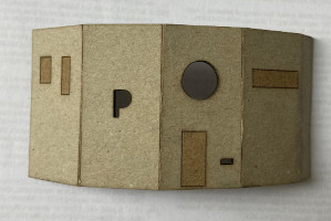
3. House#
The first assignement was to change the colors of this file. The aim of the exercise was to understand that the machine recognizes different colors as different cutting forces.
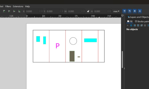
| Color | Kind of cut |
|---|---|
| blue and grey filling | engrave |
| green border | engrave |
| red line | engrave |
| pink filling and border | cut |
| black border | cut |
It is important to set the type of cut in this order in the program, especially making sure the cutting force is applied last! By the end of the process, I realized that filling the letter P with pink and the little square with grey wasn’t necessary. The machine wasted time engraving something that would be cut at the end, so be careful with that. It’s not necessary to use many colors.
5. Speed and Power Test: lasecutter’s focus, power, speed, kerf and joint clearance#
Since we didn’t have enough time in class to complete all the exercises, Lawra and I went to the fablab to print the speed and power test. We rented the machine for a few minutes, but unfortunately, our first version of the Speed and Power test was done incorrectly. We didn’t have time to redo the cut, but we know there are some improvements we could make, such as adding an extra circle and indicating the respective force and speed we used to cut each part.
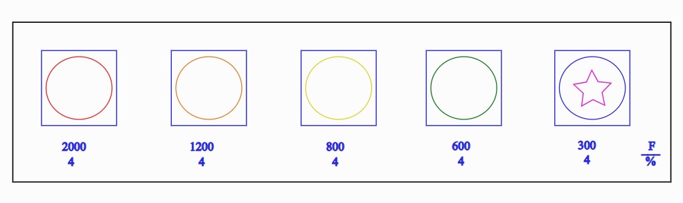
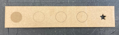
Additionally, we realized we could pay more attention to details like focus, which affects the precision of the cut, kerf, which is the width of the cut, and joint clearance, which helps ensure that parts fit together properly. These factors could significantly improve the quality of the cuts and the overall outcome of our project.
4. My Project#
For my individual project, I want to create something useful. So, I did a little research about laser-cut objects and found this:
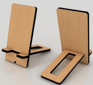
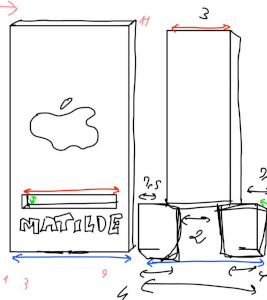
I started by drawing a sketch of my idea and doing some calculations to find the right dimensions.

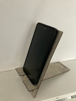
So, to cut my object, I just followed the same steps as before, and this was the final result:
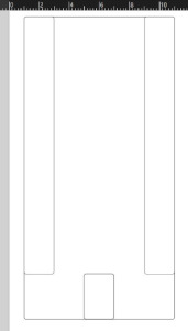
How did I design my CAD files?#
| File | Tools | Comments |
|---|---|---|
|
Rectangle tool, Star/Polygon tool, Fill | This part took a long time to engrave and cut. I shouldn’t have engraved the inside of all the stars. Instead, I should have just done the borders and even cut out some stars. |
|
Rectangle Tool | As I drew several rectangles on top of each other, the machine cut in the same place twice. I should have grouped the borders of the rectangles. |
Testing laser cutters helps optimize performance and ensure safety. Key lessons include calibrating power and speed, maintaining precision through proper focus, and ensuring ventilation. Regular maintenance and efficient design workflows improve quality, minimize waste, and enhance results.
4.2 3D Printing Repair#
We started our class by learning what Repair Café is about. Repair Café is an initiative that brings people together to repair broken or damaged items instead of discarding them. It promotes sustainability, reduces waste, and encourages skill-sharing and collaboration.
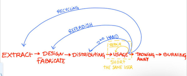
The longer the line, the more energy it costs. Therefore, repairing, being the shorter path, is easier.
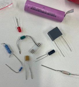
After this introduction, we learned about eletronic circuits and their components.
| Component | Description |
|---|---|
| Battery | device that stores and provides electrical energy |
| LED | is a semiconductor device that emits light when current flows through it |
| Resistor | is a passive component that resist the flow of electric current |
| Fuse | is a safety device used to protect components from excessive current that could cause damage |
| Capacitor | is a passive electronic component that stores and releases electrical energy in a circuit |
| Diodo | is a two-terminal semiconductor device that allows current to flow in only one direction while blocking current in the opposite direction |
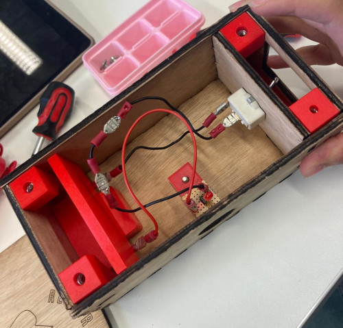
1. Exercise#
2. Project#
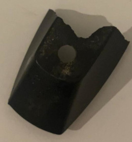
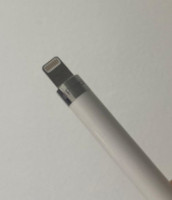
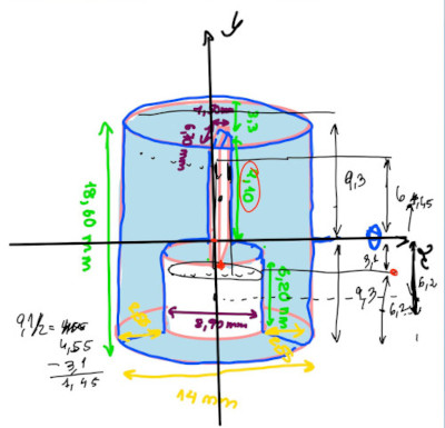
Together with Paula, I analyzed the broken part and took the pen cap measurements as accurately as possible. Afterwards, we designed the pen cap with OpenSCAD.
// file: pen cap.scad
// Autor: Matilde Peralta Gonçalves & Paula Zamorano Ceña
// Date: 29th october 2024
//License: Creative Commons Attribution-NonCommercial 4.0 Internacional CC BY-NC

$fn = 50;

difference(){
  cylinder(h=18,r=7, center=true);
    translate ([0, 0, -3.1])
  cube([1.6,7,23], center=true);
    translate ([0, 0, -6.2])
  cylinder(h=6.2,r=4.45, center=true);
}
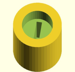
Once finished, we proceeded with the steps we learned in Module 3 about 3D printing. You can review the steps here.
After we tried to put the cap on the pen, we realized the measurements weren’t done correctly. To identify the problem, we measured again and concluded that the measurements were, in fact, correct. Later, we discovered that the issue was with the parameters we used in OpenSCAD. We made the necessary adjustments and printed the cap again.